- Last updated Jan 07, 2022
- Agricultural Irrigation, Pumping System
Introduction to combination of pumps
Centrifugal pumps can be connected in series or in parallel to provide additional head or flow rate capacity. A series of centrifugal pumps are used to overcome system head losses larger than a single pump can handle. Centrifugal pumps are connected in parallel to overcome a larger volume flow rate than a single pump can handle.
Advantage of using pumps in combination
- Lower initial cost
- Lower installation cost
- Easy to maintain
- Operating cost is low
- Energy savings
- Standby operation
Parallel Pumping
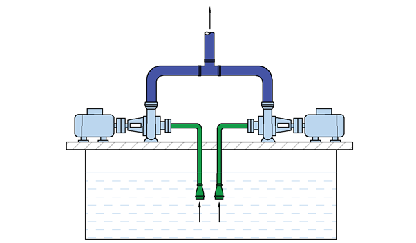
In parallel combination, the pump receives liquid from the same suction manifold and discharges into a common discharge manifold as shown in Figure 1.
When the pumps are connected in parallel, the flow rate is added to a normal head. The flow rate Qt is divided between Q1 and Q2 with respect to the pumps. Each pump develops the same head H at the corresponding capacity. Thus, the first pump with flow rate Q1 develops the same head H as the second pump with flow rate Q2.

Fig.1 - Pumps in Parallel
Features Of Parallel Pumping
- Flow rate Increases
- Pressure will remain the same
- Turn off one pump when demand drops
Pumps in Series
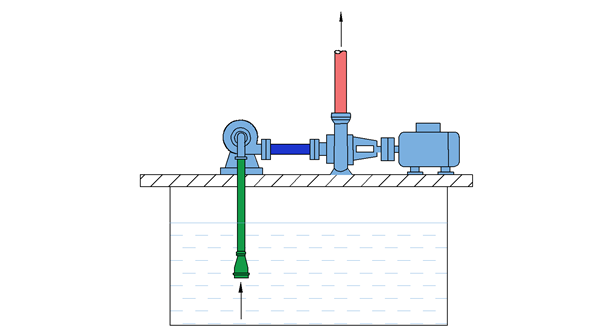
In a series combination, pumps are connected one after another. The discharge of the leading pump is connected to the suction of the trailing pump as shown in figure 2.
When pumps are connected in series, each pump has the same flow rate, but the total head developed will be the sum of the individual pump heads. Since each pump develops heads H corresponding to a flow rate Q, when connected in series, the total head developed is;
Ht = H1 + H2, where H1 and H2 are the heads delivered by the pump in series at normal flow rate Q.

Fig.2 - Pumps in series
Series pumping can reduce installation and operating costs. Series pumping with two or smaller pumps also provides a higher standby capacity to handle the overall pumping requirement. Larger pumps may have very high NPSH requirements. To avoid cavitation, a small pump can be used in series, discharging large ones into the suction nozzle. This causes an increase in the NPSH available at the larger pump suction.
Features of operating pumps in series
- The flow rate will remain the same
- Pressure will increase
- Turn off one pump when demand drops
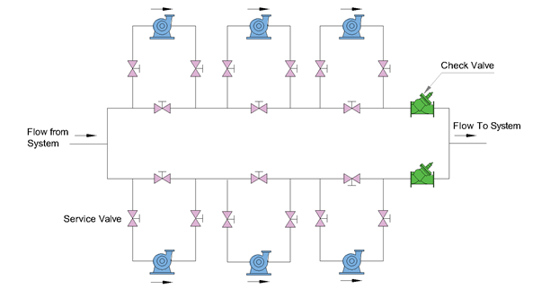
Combination of parallel & series pump application
In large installations that make conditions for future expansion, or when a relatively low flow rate for heating and a high flow rate for chilled water-cooling is required, a combination of series and parallel pumping will be used. A typical installation might look like the one in Fig.3.
